leave a message

How to Choose the Right Gravity Casting System?

Choosing the right Gravity Casting System begins with the alloy, component geometry, and production target. A system suitable for aluminum housings may perform poorly with copper alloys or thick iron parts. The decision requires more than comparing machine prices.

Casting authority John Campbell states, “The quality of a casting is determined by the quality of the liquid metal.” This principle remains practical on the factory floor. Clean melting, accurate temperature control, and stable filling conditions directly affect porosity, shrinkage, and surface finish. Check the furnace capacity, mold design, pouring method, cooling control, and inspection equipment. These details often decide whether a casting passes reliably.

Look closely at the part itself. Thin ribs, deep cavities, and uneven wall thickness may demand stronger process control. Gravity casting can offer repeatable results, but it is not automatically the best choice for every design. That matters.

Review the supplier’s documented experience with similar alloys and component sizes. Ask for process data, sample castings, dimensional reports, and maintenance records. A confident sales presentation is not enough. I would also examine cycle time under real operating conditions, not only laboratory figures. Energy use, operator training, mold replacement, and future capacity deserve equal attention.

Some choices remain uncertain until production trials begin. That is normal, and ignoring uncertainty is the real mistake. A well-selected Gravity Casting System should balance quality, flexibility, operating cost, and long-term reliability rather than chase the lowest purchase price.
How to Choose the Right Gravity Casting System?

Understand Gravity Casting and Its Core System Components

How to Choose the Right Gravity Casting System?

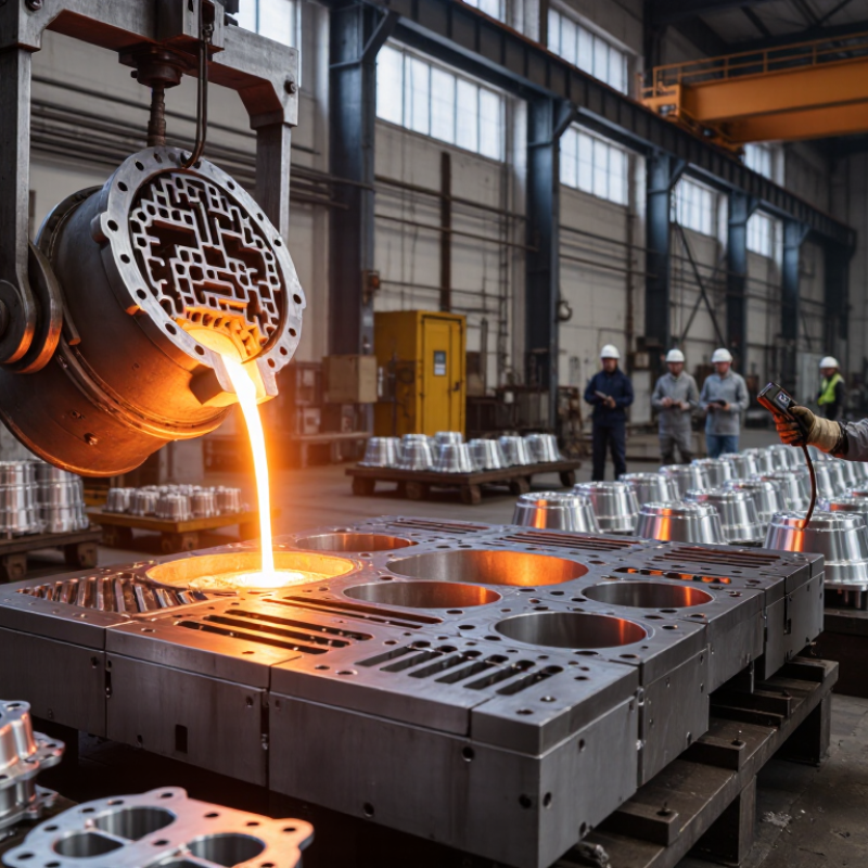
Gravity casting uses natural force to move molten metal into a reusable mold. The system looks simple, but each component affects casting quality. A furnace must maintain stable melting temperatures. A ladle should deliver metal smoothly, without turbulence or excessive heat loss. The mold needs accurate cavities, strong clamping, and suitable venting. Risers also matter because they feed shrinkage during solidification. Small design errors can create porosity, cold shuts, or incomplete filling.

Temperature control is central to the process. Operators should record metal temperature, mold temperature, filling time, and cooling conditions for every production batch. These records support reliable adjustments and easier quality checks. A practical gravity casting system should also include safe handling tools, clear inspection points, and accessible maintenance areas. Automation may improve consistency, but it cannot correct a poorly designed gating system. That is an easy detail to overlook.

Tips: Match the mold material to the alloy and production volume. Check vent locations before cutting the mold. Keep ladle movement short and steady. Inspect castings for surface defects and internal porosity. Test a sample batch before full production. No system is perfect. A design that performs well in trials may still struggle during longer runs, especially when temperature control becomes inconsistent. Periodic review is necessary.

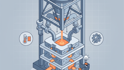
Match the Casting System to Alloy, Part Design, and Volume

A gravity casting system should fit the alloy’s flow and solidification behavior, not just its melting temperature. Aluminum alloys often suit permanent-mold processes when repeatable dimensions and medium-to-high output matter. Their fluidity, oxide formation, and feeding needs still influence gating and mold design. For brass or other copper alloys, higher pouring temperatures can increase mold wear, so tooling material and coating deserve careful review. Test the actual alloy; handbook values do not tell the whole story.

Part geometry narrows the choice. A simple, open shape may work well in a fixed mold with a straightforward pouring path. Thin walls, deep pockets, or uneven sections can require controlled tilting to reduce turbulence and help metal reach narrow features. Look closely at the thick-to-thin transitions. Those are common places for shrinkage or incomplete filling, and a clever machine cannot fix poor part design.

Production volume changes the economics. A manual system may be sensible for prototypes or short runs, while repeat orders can justify automation and faster mold handling. But automation adds setup and maintenance demands. Consider cycle time, changeover frequency, scrap, and operator skill together. A modest system may outperform a faster one when product mix changes often. I would still validate the choice with trial pours, sectioned samples, and measured dimensions. There is no perfect match on paper.

Compare Mold Types, Pouring Methods, and Filling Control

How to Choose the Right Gravity Casting System?

Mold choice should follow part geometry, volume, and surface requirements. Permanent metal molds suit repeated aluminum production and stable dimensions. Sand molds remain practical for large, complex, or low-volume parts. Plaster molds can capture finer details, but they usually need tighter moisture control.

The World Foundry Organization reported about 109.7 million tonnes of castings worldwide in 2022. That scale shows why process repeatability matters, even for smaller foundries.

Pouring method directly affects turbulence and oxide formation.

A ladle pour is flexible, but operator movement can vary between shifts. Bottom-pour systems usually reduce surface disturbance. Tilt pouring can control the metal stream more gently.

In production trials, record metal temperature, transfer time, and fill duration. A difference of only a few seconds can change the final shrinkage pattern. Small details matter.

Filling control needs more than visual inspection. Use a designed sprue, balanced runners, adequate vents, and thermal simulation before cutting the mold. Sensors can track mold temperature near thick sections.

The International Aluminium Institute reports that recycled aluminium requires roughly 5% of the energy used for primary aluminium. That benefit is useful, but recycled feedstock needs disciplined sorting and melt treatment.

No setup is perfect. I would still validate the design with sectioned samples, pressure tests, and dimensional checks. A beautiful first casting can be misleading.

Evaluate Quality, Equipment, Safety, and Operating Costs

How to Choose the Right Gravity Casting System?

Evaluate Quality, Equipment, Safety, and Operating Costs

A reliable gravity casting system should produce stable dimensions, clean surfaces, and consistent filling. Inspect sample castings under proper lighting. Check wall thickness, shrinkage marks, porosity, and machining allowance. Ask for process records, inspection methods, and repeatability data. A polished sample proves little if production results vary.

Equipment must match your alloy, mold size, batch volume, and available floor space. Confirm temperature control, pouring access, ventilation, guarding, and emergency stops. Safety deserves practical attention. Operators should not reach across hot molds or carry heavy ladles through crowded areas. Clear walkways matter. So does training. A common mistake is choosing capacity for future growth while ignoring today’s energy and maintenance costs. Cheap purchase, expensive operation. Review power use, consumables, mold changes, labor time, spare parts, and planned downtime. No system is perfect; even a well-designed line may need adjustments after installation.

Tips: Request a trial using your actual alloy and mold design. Record cycle time, reject rate, energy consumption, and operator movements. Compare these figures with realistic production targets, not optimistic estimates. Ask who supports troubleshooting after commissioning. Document every assumption. Small gaps become costly later.

Validate Suppliers and Select the Best Gravity Casting System

Choosing a gravity casting system starts with validating the supplier, not comparing brochure claims. Ask for specifications tied to your alloy, part dimensions, mold weight, and expected cycle time. A capable supplier should explain how tilt speed, pouring temperature, and mold preheating affect filling and porosity. Request trial castings made with a representative mold and production alloy. Inspect thin ribs, thick junctions, and machining allowances under consistent lighting. Ask for dimensional reports, defect images, and the inspection method behind each result. Numbers without methods are hard to trust. That matters.

Check whether the proposed system fits your floor space, utilities, and operators. Confirm lifting capacity, guarding, extraction, controls, spare-part lead times, and training in writing. Have the supplier demonstrate changeover steps, not just a machine running smoothly. Record setup time, scrap causes, and temperature stability during a trial. Compare operating needs, including molds, maintenance, and energy, rather than purchase price alone. Ask for references involving similar alloys and part geometry, then speak with the people who operate the equipment. A clean sample is useful, but it cannot prove repeatability. No test sheet is perfect. Review raw measurements and repeat the trial if results vary. Note unanswered questions, and keep trial settings, inspection records, and operator notes together for comparison.

How to Choose the Right Gravity Casting System? - Validate Suppliers and Select the Best Gravity Casting System

Use this weighted checklist to compare gravity casting systems and validate supplier claims. The suggested weights are a starting point and can be adjusted to match the part, alloy, production volume, and quality requirements.

Evaluation Area Suggested Weight What to Validate Evidence to Request Decision Benchmark
Alloy and process compatibility 15% Confirm that the system is designed for the specified alloy and gravity-fed mold process. Aluminum and copper-based alloys can require different thermal and tooling considerations. Written alloy range, process description, temperature-control plan, and examples of comparable castings. The proposed system and tooling are explicitly suitable for the project alloy and casting method.
Part and mold capacity 12% Check part envelope, casting mass, mold dimensions, machine opening, clamping arrangement, and available working space. Equipment layout, capacity specifications, mold drawings, and confirmation against the part’s actual dimensions and weight. The machine accommodates the complete mold and casting setup with appropriate operating and maintenance clearance.
Temperature control 12% Review melt-temperature measurement, mold preheating, thermal regulation, and procedures for maintaining repeatable operating conditions. Control-system description, sensor locations, calibration records, and temperature logs from a representative production run. Critical temperatures can be monitored, recorded, and controlled within the process limits established for the part.
Repeatability and process control 12% Assess repeatable mold closing, pouring practice, tilt or rotation control where applicable, and the availability of documented operating procedures. Process flow, setup instructions, control plan, sample run data, and records of corrective actions for process variation. Key process steps are defined and consistently followed; trial results meet the agreed dimensional and quality requirements.
Throughput and cycle planning 10% Evaluate the full production cycle, including mold handling, pouring, solidification, opening, part removal, and any required cooling or finishing steps. Cycle-time breakdown based on the proposed part and mold, expected operating shifts, and the supplier’s stated capacity assumptions. Capacity calculations include realistic handling and cooling time and are demonstrated during a representative trial.
Mold and tooling provisions 10% Confirm mold material, cavity layout, gating and riser approach, venting, ejection method, expected maintenance, and ownership of tooling design data. Tooling proposal, drawings for approval, maintenance plan, spare-component list, and written tooling ownership terms. Tooling is designed for the part and production plan, with a clear maintenance and modification process.
Safety and operator ergonomics 8% Review guarding, emergency stops, hot-metal handling, heat protection, safe access, lifting needs, and applicable workplace safety requirements. Risk assessment, safety-device list, operating instructions, and installation safety requirements. Identified hazards have documented controls, and required safety devices are included in the system scope.
Automation and integration 7% Determine whether manual, assisted, or automated operation best fits the production volume, labor plan, floor layout, and required process consistency. Automation scope, interface requirements, utilities list, operator training plan, and integration responsibilities. Automation level matches production needs without adding unnecessary complexity or unclear interface responsibilities.
Quality inspection and traceability 8% Agree on inspection methods appropriate to the drawing and application, such as dimensional checks, visual inspection, and specified non-destructive testing. Inspection plan, sample reports, equipment calibration records, and a method for linking results to production lots. Acceptance criteria and inspection responsibilities are documented before production approval.
Service, training, and spares 6% Check commissioning support, operator and maintenance training, troubleshooting guidance, spare-parts availability, and response arrangements. Service scope, training agenda, recommended spares list, warranty terms, and escalation procedure. Support responsibilities, response expectations, and critical spare parts are agreed in writing.
Total 100% Use the same criteria and evidence requirements for every supplier under consideration.
Scoring method: Rate each area from 1 to 5, where 1 = does not meet requirements, 3 = meets requirements with documented gaps or conditions, and 5 = fully meets requirements with verifiable evidence. Calculate the weighted score as (rating ÷ 5) × weight. Treat alloy compatibility, machine capacity, safety, and successful part trials as mandatory approval gates rather than relying on the total score alone.

Final selection should be based on the approved part specification, documented supplier evidence, and a representative casting trial. Equipment capability and production results depend on the alloy, part geometry, mold design, operating conditions, and inspection requirements.